| |


NDEI Vessel and Piping inspection for a cleaner, safer workplace.
FRP Acoustic Emission Test Report
In accordance to ASTM E1067-01
Acoustic emissions are elastic energy waves that are spontaneously released by a material undergoing deformation. Acoustic emission testing is defined as a “passive” inspection method for monitoring the dynamic internal stress redistribution within a material that occurs when an external stress is imposed on a component. The stress can be either a hydrostatic, pneumatic or thermal. In an acoustic emission test a network of piezoelectric transducers are attached to the exterior of a vessel. These sensors convert mechanical energy such as elastic waves into an electric impulse that is transmitted by cable to the AE Instrument.
As the vessel is stressed, the AE instrumentation collects signals. Parameters from each emission are measured and then stored within the system data logger. Data from each sensor is stored on separate channels along with the exact time when the event was detected. These data are analyzed both during and after the test. Acoustic emission serves an important function in the oil, chemical, paper and petrochemical industries, to name a few. It is a global non-destructive examination technique, which provides a measure of the structural severity of a defect. As such, it is complementary to other non-destructive examination methods such as radiography, ultrasonic, and visual which are used for examination of local areas. Prior to the development of acoustic emission, hydrostatic test was the principal global test. This Inspection method is designed to detect structurally significant defects and damage in vessels that can occur during fabrication and under normal operating conditions. This test will only detect defects that are stressed during the course of the test. Defects in unstressed areas and passive defects (structurally insignificant during the applied load) will not generate AE. Some of the defects than can generate AE are as follows:
- Crack Growth - Fiber breakage - Stress corrosion micro cracking / liner matrix failure - Delaminations - Entrapped air pockets / Manufacturing flaws - Inadequate design for the applied stresses. This vessel was examined in accordance with the ASTM E1067-01 Standard for Acoustic Emission (AE) monitoring of fiberglass-reinforced plastic (FRP) tanks/vessels under atmospheric pressure to determine structural integrity.
This practice is limited to tanks/vessels designed to operate at an internal pressure no greater than 0.44 Mpa absolute (65 psia) above the static pressure due to the internal contents. It is applicable for tanks designed for vacuum service with differential pressure levels between 0 and 0.06 Mpa (0 and 9 psi), and for atmospheric service.
Two separate criteria were used to evaluate the data recorded;
1) The C.A.R.P. Recommended practice is used to assess an overall status of the vessel.
2) An intensity analysis / Historic Index which dictates a severity category on a per channel per hit basis.
Exceptions: No exceptions to the ASTM standard were necessary for the completion of the acoustic emission examination.
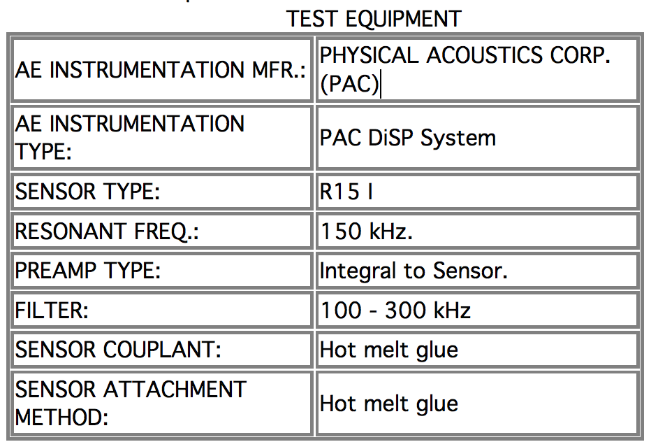
Following the ASTM E-1067-01 test procedure, once the sensors and connection cables were in position the system was connected and verified using a mechanical PENTEL Pencil 0.3 mm. Three lead breaks were performed at 4.0 in. from the center of each sensor, the results of this test were recorded and used to verify the performance and calibration of each channel.
PRE-TEST BACKGROUND NOISE CHECK
In order to establish emission levels that can be attributed to the normal background noise emission that is extraneous, the vessel was monitored ten (10) minutes prior to the start of the loading sequence. All data received during the background check and proven to be extraneous, was recorded and utilized during the post test analysis as a dataset filter parameter.
TEST TERMINATION Departure from a linear count / load relationship should signal caution. If the AE count rate increases rapidly with load, the vessel shall be unloaded and the test terminated. A rapidly (exponentially) increasing count rate indicates uncontrolled, continuing damage, and is indicative of impending failure. Test termination is solely at the discretion of the inspection technician.
LOADING METHOD AND SEQUENCE
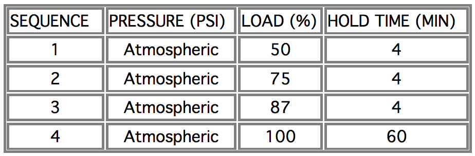
In order to perform a successful acoustic emission test, the vessel under test must be subjected to programmed increasing stress levels, while monitored by the acoustic emission testing equipment. The guidelines recommended in the C.A.R.P / ASTM E1067-01 procedure require that the vessel must be tested at a maximum of 100% of the operating level. The inspection analysis is valid only to the achieved load level. Based on this information, the following loading schedule was imposed to the vessel:
IN SERVICE VESSEL
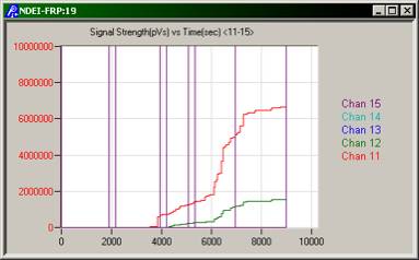
#1 EMISSIONS DURING LOAD HOLD PERIODS
PASS= No hits after 2 minutes in any hold (static load) period.
The significance of these criteria is that continuing emissions during the hold can indicate a continuing yield or damage due to creep or a growing defect. These criteria can show the presence of a significant defect when the total number of hits during each load hold is increasing with the increasing load level.
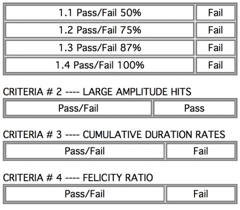
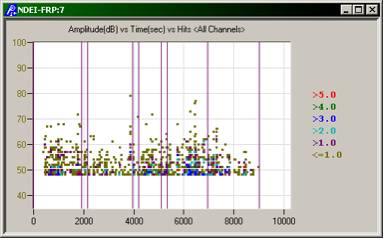
#2 LARGE AMPLITUDE HITS
PASS= <5 hits with amplitudes greater than the reference amplitude of 76Dbae.
Large amplitude hits often indicate the presence of a growing crack, fiber breakage, or significant structural damage.
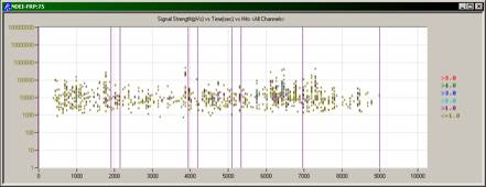
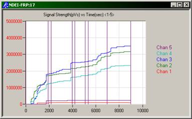
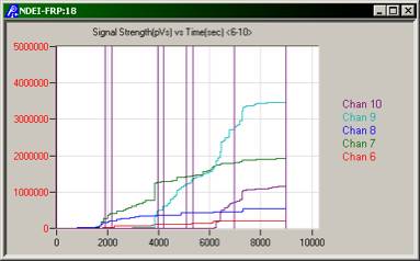
#3 CUMULATIVE DURATION PASS= Less than 1000 microseconds per channel above the test threshold during a load increase of 5 % of the operating pressure. The criterion measures the total activity. It is particularly important for detecting widespread damage such as general corrosion.
#4 FELICITY RATIO Pass= > 95% previous load The criterion ratio is important for in service vessels. The felicity ratio provides a measure of the severity of previously induced damage
#5 HIT COUNT Pass= < Nc /2
This criterion is a measure of overall damage during a load cycle Count value (Nc) in accordance to ASTM E1067-96 A2.4.4 , is equal to 5 x the sum of the total counts from 13 , 0.3-mm (2h) lead pencil breaks for each of the two lead break locations (ie. #1 in the direction of the fibers , #2 at 45 degrees to the direction of the fibers) This criterion is subjective to the specific material utilized for construction, cumulative duration has generally been utilized to replaced this criterion.
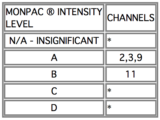
INTENSITY ANALYSIS When any sensor detects emission from a vessel that exceeds one or more of the Evaluation Criteria, the data must then be further analyzed to determine the source and intensity of the emission. Below is a general description of the intensity rating levels and associated recommendations.
N/A. The N/A identifies channels for which a meaningful channel intensity cannot be calculated because the channel only detected a small number of hits. N/A will result if a channel has 10 or fewer hits.
INSIG. Insignificant AE. Not follow-up required. Insignificant Emission. Represents a very low level of AE activity not considered to be of structural significance.
A & B. Minor defect, note for future reference on future test. Emissions with these intensities represent a low level of activity, but are considered an indication of minor defects. Sensors with the A and B intensities generally do not require follow-up action other than noting for reference and comparison with future test results.
C A significant defect requiring follow-up evaluation. Sensors in the C intensity require follow-up evaluation. This evaluation can consist of a detailed data review to more closely identify the location of the defect area and the type of defect. It may include additional inspection of the area of concern using complementary NDE techniques.
D Immediate follow-up inspection with nondestructive testing methods. These channel intensities indicate increasingly sever defects which require immediate follow-up NDE examination and repairs. After the repairs are completed, an additional AE test should be performed to verify that all defects have been repaired and that repairs are effective in eliminating of AE activity.
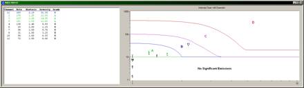
These rankings are established by processing the recorded acoustic emission from each channel through specific calculations. The first calculation “Severity” is the average relative energy of the ten- (10) largest hits received by a sensor. The second calculation “Peak Historic Index” is a running comparison of the latest emission recorded compared to the total emission received by a sensor during the test. These rankings are utilized as part of an overall analysis of the vessel, and should not be used solely to evaluate the structural condition.
TEST RESULTS C.A.R.P. EVALUATION CRITERIA IN-SERVICE FRP VESSELS
CRITERIA # 1 ---- EMISSION DURING HOLD PERIODS
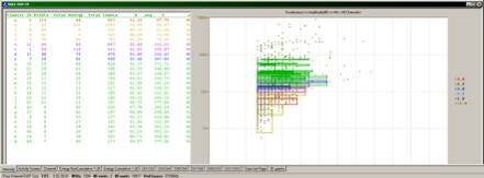
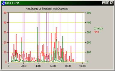
Documents and graphs generated during the analysis


| |